Những lưu ý quan trọng khi sử dụng biến tần:
+ Chọn công suất phù hợp với động cơ: Với các ứng dụng chạy tải nhẹ(Như quạt, bơm…) thì có thể chọn công suất biến tần tương đương với công suất động cơ. Còn đối với các ứng dụng tải nặng như cầu trục, máy nghiền, thang máy, nén khí… thì nên chọn công suất biến tần cao hơn 1 cấp so với công suất định mức động cơ.
+ Lựa chọn loại biến tần phù hợp với môi trường lắp đặt: vì môi trườngở Việt Nam khá nóng ẩm nên khi lựa chọn biến tần cần chú ý tới việc nó đã được nhiệt đới hóa hay chưa. Thông thường biến tần khi đã được nhiệt đới hóa sẽ có khả năng hoạt động ở nhiệt độ khoảng 50oC và độ ẩm dưới 90%RH. Ngoài ra cũng cần chú ý đến môi trường lắp đặt: thông thoáng, ko có khí gas, bụi bẩn hay chất ăn mòn…
+ Đọc kĩ tài liệu HD trước khi lắp đặt, sử dụng: vì mới loại biến tầnsẽ có cách thức đấu nối và cài đặt khác nhau nên trước khi đi vào hoạt động người sử dụng cần tìm hiểu kĩ xem loại biến tần đó đấu nối như thế nào, có cần thêm thiết bị phụ trợ nào không hay nên cài đặt những tham số nào và không nên thay đổi những tham số nào…
+ Thông thường biến tần luôn có chức năng lưu giữ các cảnh báolỗi. Khi xảy ra lỗi, người vận hành nên ghi lại những lỗi đó và tình trạng khi xảy ra lỗi để phục vụ cho công tác khắc phục sự cố sau này.

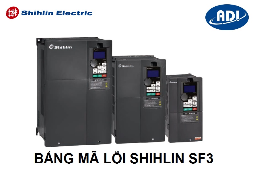
Bảng mã lỗi biến tần Shihlin SF3/ Alarm code for Frequency Converter Shihlin SF3
-
-
Code
Display on keypad
Reason
Handling method
ERROR
ground
the motor
OC0
Overcurrent when the inverter stops
The output current exceeds twice the rated current of the inverter or the load is
short-circuited
The inverter may be affected by external electromagnetic noise. Please improve the wiring.
Power off and power on again. If this alarm occurs repeatedly, please send it to the factory for repair.
(Note 1)
OC1
Overcurrent during
acceleration
(Note 1)
OC2
Overcurrent at
constant speed

OC3
Overcurrent during
deceleration
OV0
Overvoltage when the
inverter stops
The voltage between terminals (+ / P)-(-/ N) is too high or the motor is leaking to ground;
External power lines have large electrical equipment start and stop affecting grid surges
Check whether the input power supply voltage is normal. (Note 1)
OV1
Overvoltage during
acceleration
(Note 1)
OV2
Overvoltage at constant
speed
OV3
Overvoltage during deceleration
THT
IGBT module overheating
1. IGBT module accumulated heat relay action (overload warning) 2.01-03 (P.3) The setting does not match the rated frequency of the motor.
incorrect
/ △) is consistent with the motor nameplate
(Note 1)
-
Insufficient power supply voltage
-
Reset function RES is “on”
-
Poor contact between operator and inverter host
-
Internal circuit failure
-
CPU malfunction
-
Abnormal load insulation to
-
Supplied with normal power
-
Disconnect the reset switch
-
Make sure to connect the keypad with the inverter host --
-
Replace the inverter
-
Reboot the inverter
-
Check the insulation of the motor cable and the three-phase winding of
-
If there is a sudden acceleration or deceleration, please extend the acceleration and deceleration time.
-
Avoid sharp load increase
-
Check whether the motor terminals U/T1, V/T2, W/T3 are short-circuited
-
If there is a sudden acceleration or deceleration, please extend the acceleration and deceleration time.
-
Check whether the regeneration braking resistor between the main circuit terminal +/P-PR falls off
-
If the braking resistor is connected, check whether the setting values of 06-05 (P.30) and 06-06 (P.70) are correct.
-
Check motor insulation to ground
-
Improve grid quality (recommended input reactor)
-
Insufficient input power supply voltage of the inverter reduces output capacity
-
The three-phase input connection of the motor is
-
Avoid overloading the inverter for a long time
-
Recheck 01-03 (P.3) and motor rated frequency setting
-
Check grid voltage
-
Check whether the motor connection (Y
-
Check if the carrier frequency 00-11 (P.72) is set too high
THN
Motor overheating

Electronic thermal relay action
FAN
Cooling fan abnormal
Cooling fan abnormal
replace it with a new one
OHT
External motor thermal relay operation
External motor thermal relay running
1.Check whether the external thermal relay capacity matches the motor capacity 2.Reduce the load
3.Check whether the external connection
signal is disconnected or disconnected
OPT RS-485
communication port
Peripheral malfunction
Correctly set communication related parameters
It is recommended to use twisted-pair shielded communication lines and the shielding layer is properly grounded.
Check communication procedures
PUE
PU communication port peripheral
malfunction
CbE expanded
communication port
peripheral malfunction
EEP
Memory malfunction
ROM malfunction
When this alarm occurs frequently, please send it to the factory for maintenance Avoid frequent communication to modify parameters and save target frequency to EEPROM. Refer to 07-11 (P.34) and target frequency communication address H1002
to prevent premature damage.
PID
PID malfunction
system are normal.
CPU
CPU malfunction
Serious peripheral electromagnetic interference
Reduce peripheral interference
OLS
Stall prevention
protection
Motor overload
SCP
Overcurrent at short circuit
(Note 1)
-
Check whether the setting value of 06-00 (P.9) is reasonable and correct (based on the rated current of the external motor)
-
Reduce the load
-
The fan is damaged, please replace it with a new one
-
Foreign object is blocking the fan, please remove the foreign object
-
Fan wiring is broken / dropped, please
-
Communication error, exceeding the number of communication error retries
-
External noise interference
-
The communication control program logic is unreasonable
-
Communication is interrupted, exceeding the communication interval allowable time
-
Insufficient inverter and motor capacity
-
PID target value or feedback value is not set reasonably
-
Peripheral equipment failure
-
The feedback signal is not connected or disconnected during PID control
-
Replace with high-capacity inverter and motor
-
Check the feedback gain setting and reset the target value according to the feedback
-
Check whether the peripheral feedback devices (such as sensors and potentiometers) and wirings of the
-
Reduce motor load
-
Increase the value of 06-01 (P.22)
-
Short circuit on the output side
-
The inverter incorrectly reports SCP warning
-
Check whether the inverter output is short-circuited (such as motor wiring)
-
The inverter may be interfered by external electromagnetic noise. Please improve the wiring.
NTC
Module overheating
Inverter-side IGBT module temperature is too high
NTC2
Module 2 overheating
NTC3
Module 3 overheating
NTC4
Module 4 overheating
NTC5
Module 5 overheating
NTC6
Module 6 overheating
OL2
Overtorque malfunction
1.Motor overload 2.Unreasonable setting of 06-08 (P.155) and 06-09
(P.156)
BE (Note 1) Brake transistor malfunction
(Relay malfunction)
Brake transistor malfunction (Relay malfunction)
Please send it to the factory for inspection and maintenance
IPF
Power input failure
Power input failure(Missing
phase)
Please check whether the power input
is normal
CPR
CPU malfunction
CPU program malfunction
AEr
4-5/3-5 terminal
malfunction
Disconnection malfunction when 4-5/3-5 terminals given
by analog
Please refer to parameter description in 02-24 (P.184)/02-33 (P.545)
PTC
Motor overheating
Motor overheating
1.Reduce motor load 2.Modify 06-16 (P.534)
BEB
Material disconnection
Material disconnection
Check whether the signal wirings of material feedback is disconnected
rAE
relay abnormal
operation
The main circuit relay is abnormal
Please send to the factory for maintenance
GF
Output short-circuit to
ground
Output short-circuit to ground
Please check whether the short circuit to ground of the motor is normal
LF
Output phase loss
The three-phase output malfunction
Please check whether the UVW three-phase output of the inverter is
normal
HDC
Hardware detection line malfunction
Hardware detection line malfunction
Please send it to the factory for inspection and maintenance
ADE
Three-phase current sampling circuit
malfunction
Three-phase current sampling circuit malfunction
Please send it to the factory for inspection and maintenance
EbE1
Expansion card SLOT1 malfunction
The first result of inverter automatic detection is inconsistent with the next result
Check the connection of expansion board
-
Reduce ambient temperature and improve ventilation strips
-
Check whether the inverter fan is running normally
-
Check if the carrier frequency 00-11 (P.72) is set too high
-
Reduce motor load
-
Adjust the settings of 06-08 (P.155) and 06-09 (P.156) appropriately
-
Check the wiring
-
Check the parameter setting
-
Reduce peripheral interference
dPF
Driving power supply for
main circuit malfunction
Driving power supply for main circuit malfunction
Please send it to the factory for inspection and maintenance
Note 1: Do not power on repeatedly until the cause of the fault is eliminated.
-
-
Malfunction
Key points
The motor does not run
Main circuit
Load
Paramet er settings
Control circuit
Opposite motor rotation direction
The motor cannot accelerate
Unsmooth acceleration and deceleration
Excessive motor current
Speed fluctuation in operation
-
Is the voltage between terminals R/L1-S/L2-T/L3 normal?
-
Is the POWER light on?
-
Is the wiring between the inverter and the motor correct?
-
Is the load too heavy?
-
Is the motor rotor locked?
-
Is the startup frequency (01-11(P.13)) set too high?
-
Is the operation mode (00-16(P.79)) correct?
-
Is the upper limit frequency (01-00(P.1)) set to zero?
-
Is reverse rotation prevention (00-15(P.78)) limited?
-
Is the signal bias and gain (02-12~02-15, 02-25~02-28/P.192~P.199) correct?
-
Is the frequency jump (01-16~01-21/P.91~P.96) correct?
-
Is MRS function “on”? (relevant parameters 03-00~03-09(P.80~P.84 、 P.86 、P.126~P.128、P.550))
-
Is RES function “on”? (relevant parameters 03-00~03-09(P.80~P.84 、 P.86 、P.126~P.128、P.550))
-
Is the external thermal relay tripping?
-
Is there an alarm (ALARM light is on) that has not been reset?
-
Is the voltage/current signal correctly connected?
-
Are STF and STR functions correct? (relevant parameters (relevant parameters 03-00~03-09(P.80~P.84、P.86、P.126~P.128、P.550))
-
Does the wiring of the control circuit fall off or have poor contact?
-
Is the phase sequence of the wiring of the motor terminal (U/T1)/(V/T2)/(W/T3) correct?
-
Is the wiring of the start terminals STF and STR correct?
-
Is the load too heavy?
-
Is stall prevention level (06-01(P.22)) correct?
-
Is torque compensation (01-10(P.0)) too high?
-
Is it limited by the upper limit frequency (01-00(P.1))?
-
Is the acceleration and deceleration time (01-06(P.7) and 01-07(P.8)) set correctly?
-
Is the acceleration/deceleration curve selection (01-05(P.29)) correct?
-
Does the voltage/current signal fluctuate due to noise?
-
Is the load too heavy?
-
Does the inverter capacity match the motor capacity?
-
Is torque compensation (01-10(P.0)) too high?
-
Does the voltage/current signal fluctuate due to noise?
-
Has the motor load changed?
-
Is the main circuit wiring too long?
-


